Since the inception of the term “Superflat” or “F-min 100” in the early 1970s, narrow-strip concrete placements have been the industry standard for the construction of Narrow Aisle and Very Narrow Aisle (VNA), Defined-Traffic, Superflat High-Bay storage warehouse, fulfillment and distribution centers, and freezer floors.
Typically, contractors construct these Superflat slabs in long, narrow strips (11 to 22 ft. wide), striking off the concrete form-to-form by hand screed, vibratory truss screed, or laser screed. (Tolerances on these types of floors can range from Fmin 50 to 125; See excerpt Table 1.1 from ACI 360-10). These methods are used to meet the high levelness and flatness tolerances that are required for material handling equipment (MHE) to operate at their maximum efficiency, while at the same time increasing associate and facility safety.
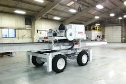
Ultimately, it is up to the facility owner to determine how their Defined Traffic or F-min concrete slabs will be constructed. If the owners don’t want corrective grinding in their defined traffic aisles, then the “narrow strip” construction method is the most viable. However, if the facility owner does not mind (and some don’t mind) having minor spot grinding here and there, with overages ranging from ~0.030-in (1 mm) to ~0.125-in (3 mm) in the MHE wheel paths, the project can be completed earlier with wider placements. How can this be done? 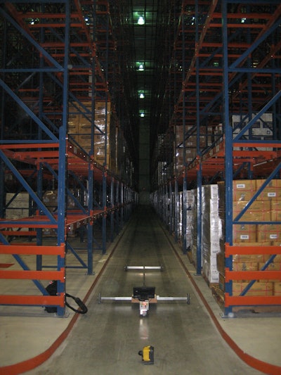 Pictured is the F-min Profiler in an operational freezer to show how working lift truck wheel paths are emulated. The temperature in the freezer is -4 degrees F.
People and equipment
On every project, it’s better for placing and finishing crews to be trained in the basic fundamentals of concrete, and having your employees become certified as ACI Flatwork Technician/Finishers is a great way to do so. However, to place and finish floors with high F-min tolerances you must also have well-trained crews that have an understanding of how everything they do (or don’t do) impacts the next step in the process and, in turn, the final results. To assist, it’s recommended finishers become certified as ACI Specialty Commercial/Industrial Concrete Flatwork Technicians/Finishers. This certification provides proof that an individual has the basic training necessary to construct superflat floors.In addition to skilled employees, it’s also good to employ the services of a specialized and experienced floor consultant. They can assist with mix design review and adjustments, the planning and pre-construction process, and some can even provide additional hands-on place and finish training for your crews. Great finishers can become exceptional finishers in just a few days with hands-on training from the right consulting firm.
Not to be overlooked is the importance of the equipment used. It’s imperative that high quality, well calibrated and dependable equipment be selected to accomplish the task at hand. This is the case with your choice of screed (laser or truss) and trowel machines (walk-behind or ride-on). For screed selection, special consideration should be given to accuracy. In regards to trowel machines, different trowel sizes, weights and engine types will be needed for the various stages of the finishing process. For instance, panning operations require a diesel machine that has the torque to pan without bogging down while also having the ability to control blade speed through softer paste or paste that has become hard enough to bring to a shine.
Pre-slab meeting
An essential part of every successful quality concrete floor project, especially when levelness and flatness is a concern, is a pre-slab meeting. For this meeting to be of benefit, it requires the attendance and the full cooperation from the owner or owner’s representative, general contractor, engineer, concrete contractor, concrete producer, floor consultant, floor testing laboratory and other related members of the construction team.
Discussed in this meeting are all aspects of the floor placements, including but not limited to: jobsite access, placement rates (yards per hour), placement method (pump or chute), mix design, allowable slump, onsite slump adjustment, finish floor and form elevations, floor testing methods and acceptable testing data collection devices.
Critical issues and concerns of all parties are openly discussed and any adjustments required to allay those issues or concerns are agreed upon. For reference, the American Society of Concrete Contractors (ASCC) has a very detailed pre-slab meeting agenda available as a reference document. 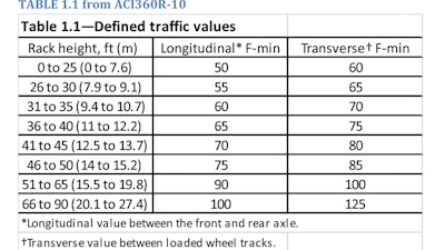
Delivery, mix and slump
Critical to successful F-min placements is having a placement “traffic controller.” Their sole responsibilities are to oversee:
- The direction of mixer-truck traffic.
- The checking of batch tickets to ensure that batch weights are within tolerance.
- Slump and temperature testing of every truckload just prior to placement. This will ensure proper sequencing of trucks and virtually eliminate the possibility of placing an out-of-tolerance load.
The ready mix concrete producer also plays an integral role. Proper timing and spacing of delivery as well as slump consistency is very important. Variable set-times and slumps will adversely affect the final profile elevations of the aisle due to differential shrinkage. Therefore, experience has shown that in regards to concrete slump:
- Slump variation should be within +/- ½” of the specification.
- Every truck should be slump tested instead of every 3 to 5 trucks.
- Major field adjustments of out-of-tolerance loads usually result in a finishing problem. It may be best to send the load away or use it on site in another application
A mix design containing well graded aggregates is also essential. The finishers need enough paste to perform the re-straightening and final finishing work necessary to meet the high flatness and levelness tolerances, but they also need properly proportioned aggregate to minimize differential setting. On a related note, varying slab thickness can cause the concrete to bleed and set at different rates, leaving hard or soft spots that are difficult to finish to a tight tolerance. Therefore, to make the slabs thickness consistent it’s recommended the finish gradework of the subbase be done using a laser grading machine with an elevation tolerance of plus or minus 1/4 inch.
Strike-off considerations
Even the smallest variations in strike-off and screed accuracy can cause major differences in achieved F-min values.
Therefore, screed operators should make sure their machines are calibrated prior to every concrete placement. Laser screed operators should confirm all electronic or hydraulic units are working properly and are set to factory specifications. They should also check the machine head (plow, auger, and vibrator) to confirm its settings and straightness are set to the needs of the placement.
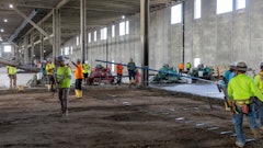
Laser screed operators should also understand the rack/aisle layout, since the testing of the F-min aisles will follow the direct wheel path of the VNA truck (usually the center of the aisle). To assist, it’s usually helpful to locate the aisles by spray painting lines and using flags or setting rebar pins with survey whiskers. You may also find it helpful to assign a “spotter” to work with the screed operator in keeping track of rack/aisle locations. The operator should reach out and pull shorter passes (running parallel to the aisle), which will allow the screed head to set down in the rack space and pull through the aisle. These simple yet effective methods will keep screed head “touchdowns” from occurring in the aisle, thereby eliminating their potentially adverse effect on the finished floor elevations (resulting in corrective grinding).
Whether using a truss or laser screed, it’s vital to follow behind the screed operations with a check rod or highway straightedge (often called a bump cutter). The proper use of these tools allows a finisher to remove high spots and fill low spots while the concrete surface is still plastic.
Finishing process
The machine portion of the finishing process starts with an initial float pass using a walk-behind power trowel (with float shoes) or a ride-on power trowel (with float pans). As soon as the surface will support their weight, finishers should then begin re-straightening the slab using a bump cutter. However, finishers should only walk on the slab in the center of the area that will be under the future racks. In some cases (like when there are curbs under the racks), finishers could even begin walking on the slab when they are leaving ¼” deep footprints.
The re-straightening process continues with ride-on trowels equipped with float pans, and then the aisles are bump cut repeatedly to remove any high spots and fill any low spots. The panning and bump-cutting process is followed by an initial pass with a ride-on trowel machine outfitted with combination blades. After this machine pass, the highway straightedge is used one final time to shave off any remaining irregularities or minute bumps (fine tuning). This is an important step because a 1/16-inch variation can be the difference between an F-min 50 and F-min 100 floor. Following this step the slab is finished by ride-on trowel machines outfitted with combination blades, resulting in a shiny hard trowel surface (burnished).
Measuring up
There are a number of different devices that testing labs can use to measure flatness and levelness (FF/FL) of random traffic floors some of which have been used on defined traffic F-min floors.
Some devices are point-to-point elevation data collectors that one “walks”, while others “roll” automatically or are “pulled” along the MHE wheel paths (See note 2 in ASTM E 1155). While the accuracy of each data collection method is debated within the industry and by their respective manufacturers, an obvious difference between the available devices is the speed of the F-min results.
While each gives you some immediate feedback as it relates to FF/FL, only one, a Profileograph, will provide immediate F-min numbers for both longitudinal and transverse profiles. Some of the other types of devices require downloading information into a specialized program or sending the data collected off to an outside consultant to calculate the F-min profiles and numbers. (Which can take hours or days.) In most instances, this limitation will impact the timeliness of contractor finishing process adjustments, corrective grinding or project completion.
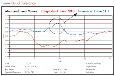 This is a chart from a floor that was out of tolerance at a distance of 95 ft. - 102 ft. Notice the Transverse F-min value before correction.
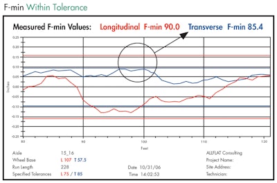 This is the same chart as above, after grinding down the bump. Notice the F-min value after correction.
‘Proof is in the project’
A good example of the success that comes from following the suggestions outlined in the previous paragraphs is the Preferred Freezer project in San Leandro, Calif., owned by Chill Build LLC. The concrete contractor on the project, Gessick Concrete of Sacramento, Calif., was tasked with constructing 185,000 square feet of VNA warehouse with a specified F-min 80 for both the longitudinal and transverse limitations.
Gessick set the goal to place and finish the defined traffic aisles using the wide bay approach with minimal grinding. Placement widths varied from 45 to 63 feet with lengths averaging over 400 feet. (These widths contained either three or four VNA per placement).
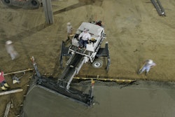
For equipment, Gessick chose to use a Somero laser screed with a 12 foot screed head as well as 8- and 10-foot diesel and gas Wacker-Neuson trowel machines. In addition to the previously outlined re-straightening procedures, Gessick also re-straightened the slab with a proprietary, collaboratively designed, ride-on trowel machine mounted bump-cutting unit.
When it came time to measure the Preferred Freezer placements against the F-min specification and render a certification for compliance, a floor flatness and levelness testing firm with a qualified, onsite technician was selected.
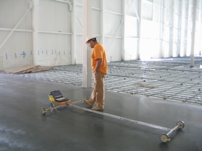
The testing firm operated a wheelbase adjustable, digital, dual-axis differential Profileograph, the F-min Profiler, to match the exact wheel path of the intended MHE. This allowed for immediate measurement results and layout of necessary spot grinding in out-of-tolerance areas.
As planned, the construction team was able to meet the schedule while minimizing the grinding cost (to meet the F-min 80 tolerance). What were the final results?
On average 3 percent of each of the 33 aisles totaling 12,276 linear feet required grinding to meet the F-min 80 specification. By comparison, other wide-bay placement methods would have endured higher overages.
Eight of the aisles measured F-min 100 or higher in both transverse and longitudinal directions.
Conclusion
No project is without challenges, but an open minded and well trained concrete contractor and crew can meet or exceed a facility owner’s expectations every time by using proper planning and construction methods, high quality tools and equipment, employing an experienced floor-consulting firm, and a testing firm that can provide quick and accurate data. This, along with durable design will result in a facility that will meet the owner’s needs for years to come.REFERENCES
ACI 117-10, “Specification for Tolerances for Concrete Construction and Materials and Commentary,” American Concrete Institute, pp 30-44ACI 302.1R-04, “Guide for Concrete Floor and Slab Construction,” American Concrete Institute
ACI 360R-10, “Guide to Design of Slabs-on-Ground,” American Concrete Institute.
ASTM E 1155-96 (2008), “Standard Test Method for Determining Ff Floor Flatness and Fl Floor Levelness Numbers”
About the Authors: Bryan M. Birdwell, is part owner of Birdwell & Associates LLC, a firm with offices in Lakeland, Fla. and Indianapolis, Ind. that specializes in contractor training as well as designing, consulting and constructing jointless and reduced joint concrete floors and paving along with high tolerance Superflat floors.
David G. Fudala, is the founder and CEO of ALLFLAT Consulting, Inc. headquartered in Carlsbad, Calif. His firm provides specification writing and review, contractor training worldwide and flatness and levelness measurements for FF/FL and F-min floors.
Birdwell and Fudala are active members of ACI.

![Fcp Racatac Chair 10893876[1]](https://img.forconstructionpros.com/mindful/acbm/workspaces/default/uploads/2025/10/fcp-racatac-chair-108938761.10l0At5WXv.png?auto=format%2Ccompress&bg=fff&fill-color=fff&fit=fill&h=100&q=70&w=100)



![Fcp Racatac Chair 10893876[1]](https://img.forconstructionpros.com/mindful/acbm/workspaces/default/uploads/2025/10/fcp-racatac-chair-108938761.10l0At5WXv.png?ar=16%3A9&auto=format%2Ccompress&bg=fff&fill-color=fff&fit=fill&h=135&q=70&w=240)
